|
|
|
Our Tech Examples Applications FAQ Index Sales
|
|
|
3D Images Using Color Structured Light |
Applications include height measurement, shape and topography measurement, object recognition, surface defect detection and classification, IC lead coplanarity and solder paste thickness measurement.
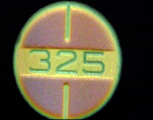 This is a CSL image of a popular analgesic tablet. The flat, upper tablet surfaces appear as purple half moons divided by green vertical bars produced by
grooves in the surface. The flat, yellow-orange slot, located approximately
0.007" below the upper tablet surface, contains the engraved number 325. The
edges of the tablet are slightly curved as shown by the yellow and green rings.
Total relief over the tablet surface is approximately 0.015".
This is a CSL image of a popular analgesic tablet. The flat, upper tablet surfaces appear as purple half moons divided by green vertical bars produced by
grooves in the surface. The flat, yellow-orange slot, located approximately
0.007" below the upper tablet surface, contains the engraved number 325. The
edges of the tablet are slightly curved as shown by the yellow and green rings.
Total relief over the tablet surface is approximately 0.015".
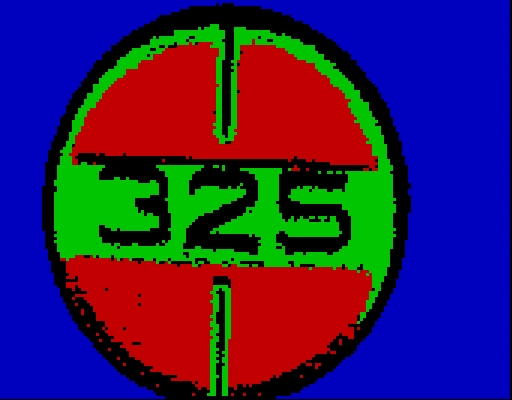
This is a WAY-2C interpretation of the above CSL image. In this case WAY-2C was trained to recognize the purple color distribution, the yellow distribution and the black surround. To simplify training, all other colors in the CSL image were grouped in a single additional category represented by black in the interpretation. The slight blurring of the tablet edge and numbers is the result of scanning a 3 by 3 pixel element of area over the tablet surface in color recognition.
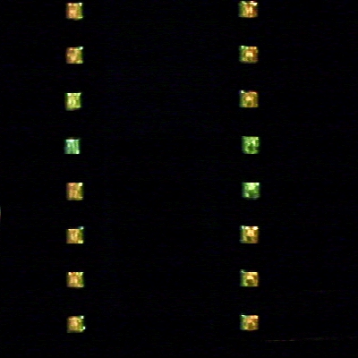
This is a CSL image of an integrated circuit package with 50 mil pitch, gull wing leads for surface mount use. The sixteen colored square areas are the nearly flat lower surfaces of the leads that are placed in contact with solder paste on pads on a printed wiring board (PWB). These surfaces must be coplanar within about +/- .002" for successful soldering. The CSL sensor was deliberately set so that only the flat surfaces appear in the image, simplifying interpretation. The color differences for leads of different heights are obvious in the JPG version of this image which can be viewed by clicking on the thumbnail version to the left .
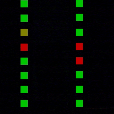
This is a WAY-2C interpretation of the above image. WAY-2C was first trained on eight planes each 0.001" apart. The green squares in the interpretation correspond to leads that are essentially coplanar, the yellow square to a lead that is approximately .001" above the green plane (above the plane of the PWB) and the red squares to leads that are approximately .002" above the green plane. The CSL image could also have been interpreted to determine if the leads meet X and Y specifications.
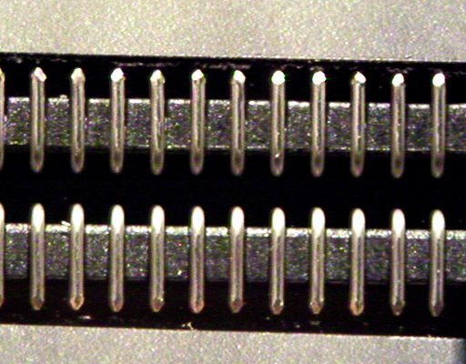
 The first image of this pair
is a conventional color image of a connector
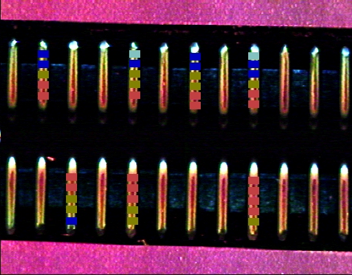
with round wire leads. The second image shows the same connector as observed
in CSL with heights measured at several places along several of the leads. Color tag intervals are 0.001". It illustrates how changes in height of the lead parallel to the long axis can be measured while ignoring the curvature at right angles to it.
The first image of this pair
is a conventional color image of a connector
with round wire leads. The second image shows the same connector as observed
in CSL with heights measured at several places along several of the leads. Color tag intervals are 0.001". It illustrates how changes in height of the lead parallel to the long axis can be measured while ignoring the curvature at right angles to it.
|
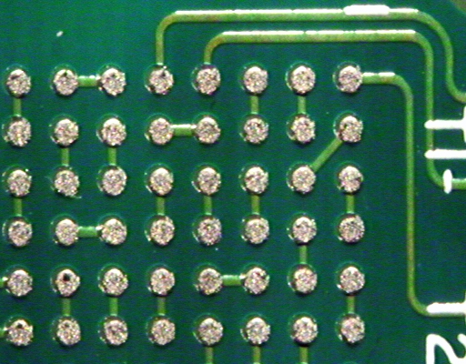
 A related application of CSL is measuring the height of solder paste.
The first image shows a ball grid array with solder paste applied, imaged
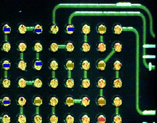
in conventional light. The second image shows the same array in
color structured light with the heights of alternate pads determined using
WAY-2C. Again the interpretation intervals, indicated by color tag intervals,
are approximately 0.001".
A related application of CSL is measuring the height of solder paste.
The first image shows a ball grid array with solder paste applied, imaged
in conventional light. The second image shows the same array in
color structured light with the heights of alternate pads determined using
WAY-2C. Again the interpretation intervals, indicated by color tag intervals,
are approximately 0.001".
|
 This shows a typical CSL system configuration.
The sensor is a simple, low cost device based on geometrical optics
principles. Height range and height resolution can be varied easily. In general
height resolution is about 2% of height range which can extend from about
0.015" to as much as several inches. Sample rates vary from application to
application and are generally determined first by materials handling requirements,
then by CSL image acquisition times and finally by WAY-2C
image interpretation times. Suitable sample rates usually can be achieved.
This shows a typical CSL system configuration.
The sensor is a simple, low cost device based on geometrical optics
principles. Height range and height resolution can be varied easily. In general
height resolution is about 2% of height range which can extend from about
0.015" to as much as several inches. Sample rates vary from application to
application and are generally determined first by materials handling requirements,
then by CSL image acquisition times and finally by WAY-2C
image interpretation times. Suitable sample rates usually can be achieved.
|
| For more information on CSL contact: | ||
|
Robert K. McConnell 14 Stevens Terrace Arlington, MA 02174
(781) 641-0605 |
||